
R&T Concealed Cistern INSTALLATION
List of main installation accessories
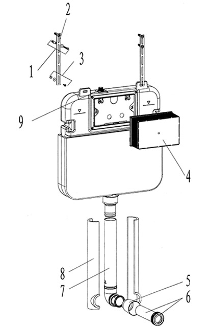
| No | Description | Qty | Function |
|---|---|---|---|
| 1 | Expansion screw | 4 | Mounting of iron bracket |
| 2 | Iron bracket | 2 | Fixation of concealed cistern |
| 3 | Screws | 2 | Fixation of concealed cistern |
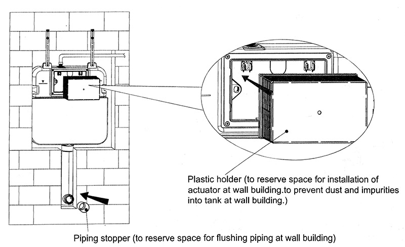
| 4 | Plastic holder | 1 | To reserve space for installation of actuator at wall building To prevent dust and impurities into tank at wall building |
| 5 | Piping stopper | 1 | To reserve space for flushing piping at wall building |
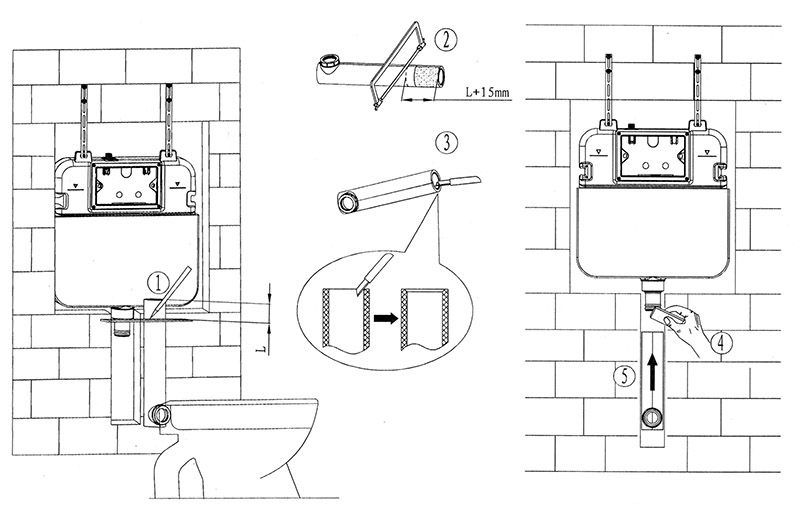
| 6 | Flushing piping | 1 | To join cistern into ceramic bowl (cutting in accordance with wall thickness) |
| 7 | Connecting tube | 1 | Water inlet to ceramoc bowl |
| 8 | Tube cover | 2 | To protect connecting tube |
| 9 | Angle valve | 1 | Fill valve inlet and shut-off |
Important instruction:
1. Please adhere to the following installation instructions.
We shall not be responsible for failures and loss that are contributed to improper installation.
2. Please confirm the fixation location of cistern prior to installation and obtain the finished floor surface.
Draw FEL on installation wall and follow it as baseline from ZERO (0) level.
3. The instructions have been composed based in the latest producct specifications.
We reserve the right to make modifications to the packaging and specifications without providing prior notification.
Notes:
1. Mount before bricks building.
2. All size unit in millimetres.
3. Follow the material product, should there is an unconformity with drawing.
FFL – Finished floor
1. General dimension and water supply drawing
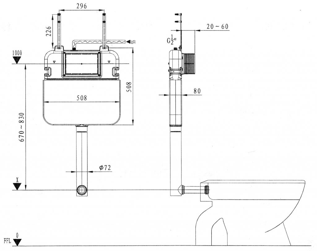
Water supply to cistern (water supply should be connected to angle valve inside cistern)
2. Building the mounting wall, drilling and installation of expancion screw
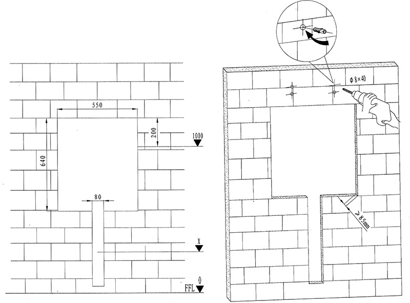
Follow the practical location of iron bracket to drill properly.
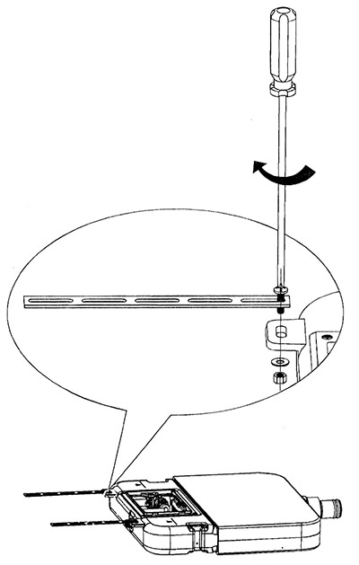
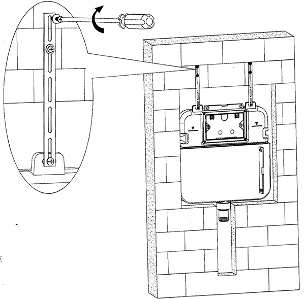
3. Installation of iron bracket
4. Installation of consealed cistern
5. Installation of connecting tube
6. Mounting of installation accessories
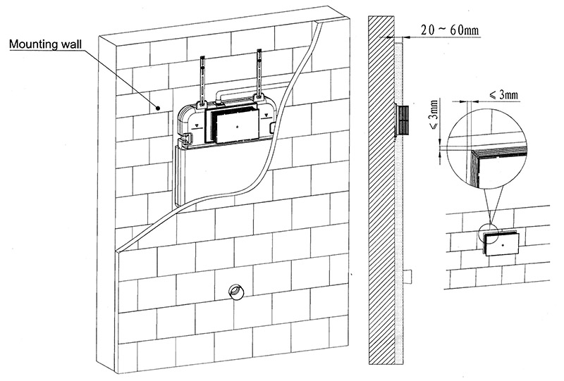
7. Wall thickness range 20-60 mm (from mounting wall surface to finished wall)
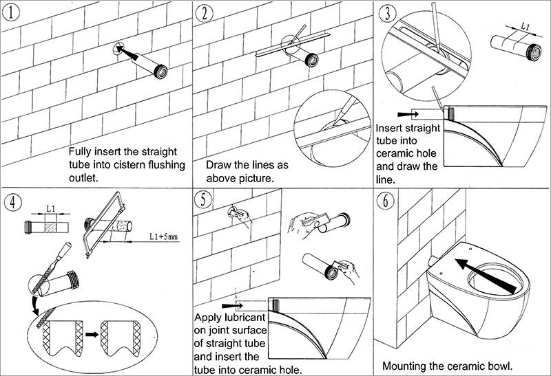
8. Installation of straight tube
9. Internal flushing mechanism assembly drawing
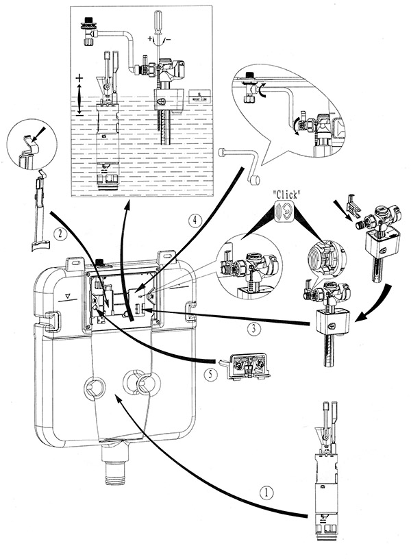
The internal flushing mechanism are already well-assembled and above picture only for reference.